 |
Complete solution to pressure and vacuum measurement and calibration |
||||||||||||||||||||||||||||||||||||||||||||||||||||||||||
News > Methods for certifying measurement equipmentINTRODUCTION Like any other piece of equipment, a measurement artifact must be maintained. Obviously, it has to be in working order in general. However, what is more important is that it be operating within specified parameters and providing measurements that are traceable to a known source or sources. This paper provides a general overview of calibration and certification. It also discusses some key terminology and methods.
BASIC TERMINOLOGY
Metrology is the doctrine of measuring and includes three major subjects: the international definition of units, realization of the unit by means of scientific methods, and the establishment of traceability for the documentation to the accuracy of the measurement. Metrology is also defined as the science that deals with measurement. Metrology is important because it is the basis for calibration, or certifying, all measurement equipment. Legal metrology, which is used in many industries, is defined as securing the accuracy of a measurement, when the measurement could have any influence on human health or safety and the transparency of financial transactions. This is evident in custody transfer applications and is one of the main reasons that having certified equipment traceable to a standard is necessary and also requires understanding by the parties involved in the transaction.
A measurement, as defined by BIPM/ISO, “Is the set of operations having the objective of determining the value of a quantity.” It sounds complex but essentially means taking a reading where that reading is easily understandable and shows what and how much. A calibration, by contrast and as defined by ISO10012 is, “The set of operations which establish under specified conditions the relationship between values indicated by a measuring instrument or measuring system, or values represented by a material measure or reference material, and the corresponding value of a quantity realized by a reference standard.” Again, sounds fairly complex but it ties to the measurement in that it specifies particular conditions and defines the system used for determining how much was measured and then goes to the next level to standardize that measurement so that like measurements are comparable to a known standard. METHODS OF CALIBRATION There are two basic situations for performing a calibration: in the field and in a lab. The field calibrations are performed in situ and the conditions are other than stable and controllable. There are three basic types of field calibrations: Line/End-to-End/Complete Loop, Separate Line/Separate Loop, and Comparative/On Line Process. These are discussed in the following paragraphs. By comparison, lab calibrations are performed in a controlled environment and under very controlled conditions and typically concentrate on a sensor or a measurement artifact.
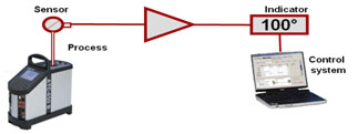 Line/End-to-End/Complete Loop Calibration
This method is used to test the entire system from sensor through to the read-out. It allows for all inaccuracies to be collected in one calibration result and therefore minimizes the risk of accumulating errors after a calibration. There is only one reference instrument necessary which makes for a small collected uncertainty. It also makes for easier paperwork. This approach does have drawbacks in that it does require portable calibrators and can, in most cases, limit the calibration to one instrument at a time. The major disadvantage is that it most often causes downtime in a production environment since the instrument must be taken out of service.
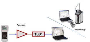 Separate Line/Separate Loop Calibration
This method is used to test the sensor and the loop separately. This can only be used when a sensor can be tested outside of the loop associated in the process and is sometimes used when calibrated spares are maintained. This does allow for a fast on-site calibration in that only the loop is tested electronically. That shorter on-site calibration time means that there is less downtime in a production facility as well as having the sensor calibrations performed when it is convenient: both are desirable conditions. The downside is that the error must be calculated from both procedures and two certificates must be maintained to cover the full calibration.
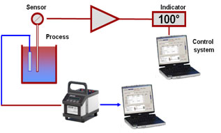 Comparative/On-Line Process Calibration
This method is used in cases where the sensor can not be removed from the process or the facility can not have down time. All of the inaccuracies are collected in a single certificate and documentation is easy. However, the significant drawback is that the process has limited variability so the amount of data points used typically suffers when using this approach. This would also require that there is an extra thermal pocket or pressure tap for the reference instrument.
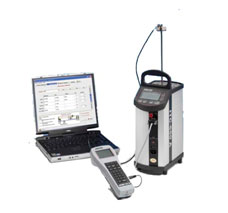 Lab Calibration
This method is used where possible to calibrate sensors and potentially the loop instruments outside of the process area. This is also the method for calibrating reference instruments. Typically, automated calibration processes are used and this requires little hands-on time for the staff. The calibration may be carried out as a schedule permits time and this also establishes calibrated spares for fast and trusted replacement.
UNITS OF MEASUREMENT
Engineering units are a precisely specified quantity in terms of which magnitudes of other quantities of the same kind can be stated. Simply put, what is Y and how many X units are required to make up a Y according to an online resource. These are used to quantify measurement parameters so that they are measured in a uniform manner regardless of location. A physical constant is a unit derived from a physical principle and is typically the basis for the system of engineering units. The speed or wavelength of light is an example.
These are very important as the units of measure are the base part of any measurement. These determine the base amount of any measured parameter. The number of units is what specifically constitutes the measurement.
The physical fundamental units are defined by Le Système International d’Unités and are the 7 fundamental SI units agreed upon internationally and can describe all physical phenomena.
From those 7 units, we have the derived units.
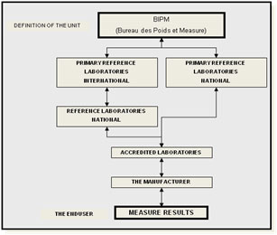
Designated organizations maintain the references for the units of measure. In the USA, the Commerce Department is responsible for the maintenance of the standards. The National Institute of Standards and Technology is the division of the Commerce Department directly responsible. Other countries have their own standards organizations. Calibration of a measuring instrument to the reference standards establishes Traceability.
 Conversion tables and software may be used to convert one unit to another provided that the conversion is within the same parameter. It is very important to use exact conversion factors. ISO Standards 8000 “Quantities and Units” and NIST Special Publication 811, 2008 edition “ Guide for the Use of the International Systems of Units (SI)” both describe the proper conversion factors and the use of the same. The NIST publication is available at no charge and may be downloaded from their website.
TRACEABILITY AND ACCREDITATION
Traceability and accreditation are two very different things. As discussed, traceability documents an unbroken chain for the measurement parameter back to a recognized standard for that parameter. Accreditation deals with the method for performing a calibration and documents a repeatable process for the same. ISO/IEC 17025 “General Requirements for the Competence of Testing and Calibration Laboratories” is one of the more recognized of the accreditations internationally. It is commonly referred to as Guide 25 and establishes stringent requirements for calibration reports, uncertainty information and calibration methods.
INSTRUMENTS AND STANDARDS
Understanding the use of an instrument and the type of an instrument are key to the process of certifying instruments and of having instruments certified.
A calibrator is an instrument with the capability to generate a known physical unit with known accuracy. A measuring instrument is a tool used in addition to a calibration instrument. The measuring instrument can only measure a parameter or electric signal. Calibrators are used to calibrate measuring instruments. Measuring instruments are only capable of checking and not calibrating parameters.
A reference standard, according to ISO/BIPM/OIML, is, “A standard, generally of the highest metrological quality at a given location, from which measurements made at that location are derived.” These instruments would most certainly be traceable to a standard. Another type of standard that may be in the chain would be a measurement standard and ISO10012 defines that as, “A material measure, measuring instrument, reference standard, material or system intended to define, realize, conserve or reproduce a unit or one or more values of quantity in order to transmit them to other measuring instruments by comparison.” Both of these types of units establish measurements that are utilized as a standard for measurements, calibrations, or transfers made from one site to another typically through a physical means. In the process of legal metrology, where something may be transferred from one organization to another, a consensus standard may be established through agreement of both parties. A consensus standard is an artifact or process that is used as a de facto or consensus standard by mutual consent between parties in cases where no national standard or physical constant is available.
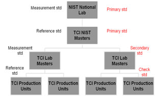
In contrast to the general standards definitions in the preceding, there are other defining qualities of standards more widely utilized. A primary standard is operationally defined by ISO10012 as, “A standard which provides a magnitude or value of the highest accuracy (lowest) uncertainty in a given metrology discipline, for a given parameter or quantity.” Strictly speaking, a primary standard is a device that is directly traceable to the physical standards and all errors are eliminated or evaluated. In comparison, a secondary standard is a reference instrument that typically is not directly based on the fundamental units of measure: the parameter measured is translated into a signal for reading such as electrical or a dial gauge. ISO/BIPM/OIML defines a secondary, or working standard, is, “A standard whose value is fixed by comparison with a primary standard.” The relation of a secondary standard to a primary standard is true regardless of the accuracy of the instrument. A transfer or check standard is one used as an intermediary to compare standards, material measures or measuring instruments: this is the level of a typical field calibrator.
 Instruments should be chosen based on the task at hand. A primary standard may not be the better choice for the field calibration of an analog indicator. A rule of thumb is to have a 4:1 ratio of accuracy of the calibrator to the instrument being calibrated. With the improvements in instrument technology, this may not always be recognizable; however, a minimum of 2:1 should be used. In addition to the accuracy specification, the choice of standards should also include future use considerations, confidence, and the compliance with internal and external quality or regulatory systems.
FACTORS IN MEASUREMENT
Having a working knowledge of factors in measurement is vital and without it, measurement and calibration can not fully be understood. One term that will always be discussed, analyzed and debated is accuracy.
Accuracy and Uncertainty
Accuracy is defined by ISO10012 as, “The closeness of the agreement between the result of a measurement and the true value…” This is in actuality a qualitative term without a numerical value. However, the industrial and operational use of this term has come to describe a characteristic with a numerical value. ISO/IEC 17025 has brought the defining term of uncertainty into the language of measurement and calibration and this shift will provide more clarity as it becomes more widely accepted. Until that time, users will continue to review specifications with an accuracy value stated for the performance of an instrument.
Uncertainty is a term used to quantify the potential deviation of a measuring device or instrument from nominal or specified value. This is a quantitative term and has numerical value. This is determined statistically and is reported as a Type A uncertainty and includes a confidence level or coverage factor. If the uncertainty is determined in a manner other than through the use of statistics, it is called a Type B uncertainty.
So, for now, accuracy is typically referred to as the maximum expected measuring error for a given unit against a known value. Unfortunately, this is typically all of the data that is given for consideration. There are factors within that performance statement which are rarely mentioned: hysteresis, linearity, and repeatability. Hysteresis is the property of an instrument whereby its response to a given stimulus depends on the sequence of the preceding stimuli: commonly discussed as upscale versus downscale. Linearity is ability of an instrument to maintain a constant deviation throughout the measurement range. Repeatability is sometimes called precision and refers to the quantified, repeated assessment of the same parameter with consistent results. All of these attributes factor into the accuracy performance of an artifact or measuring instrument and must be considered.
Accuracy Expressions
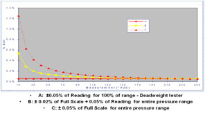
There are two typical methods to mathematically express accuracy in the instrumentation industry. They may be used alone or in combination. These are percentage of full scale and percentage of reading. Percentage of full scale is typically applied to secondary standards and yields a performance that has an error that is consistent throughout the operational range. For example, a unit with a ±0.1% of full scale accuracy on a 3,000 psi instrument would read accurate to ±3.0 psi at any place from 0 to 3,000 psi. A percentage of reading instrument would have a smaller error lower in the scale of the unit. For example, a unit with a ±0.1% of reading accuracy on a 3,000 psi instrument would have an error of ±0.1 psi at 100 psi but ±3 psi at 3,000 psi. The percentage of reading accuracy statements are typically used for primary standards. Combination specifications are starting to be used more frequently and they basically designate that there is a floor specification to the overall accuracy performance of the unit below which there is an expected constant error.
Understanding the accuracy statement is very important. Knowing whether other factors are included in that overall accuracy is just as important.
Other Considerations
Some other factors that are important deal with the actual readout on the device itself and the ability to view a response to stimulus. Scale resolution is the smallest or least scale division on the display. The resolution should support visualizing the stated accuracy of the instrument. If the resolution does not allow for viewing the stated accuracy of the instrument, it is difficult to verify that accuracy statement. The industry standard allows for one half of the smallest division to be considered. Scale sensitivity or sensitivity is the proportional, linear, least scale displacement. Again, if the stimulus can not cause the instrument to deflect in a slight enough method to allow for viewing of the stated accuracy, then verification is difficult. Scale discrimination is simply the ability to provide the smallest perceptible indication from a stimulus.
 RESULTS
Results should be documented for future reference and review. Most quality systems and auditing agencies require that documentation be maintained for critical calibrations. A part of that documentation is the certification for the site reference standards: to include performance, accuracy or uncertainty, and traceability for the calibration. Without documentation as evidence, all downstream calibrations are in question. |
|||||||||||||||||||||||||||||||||||||||||||||||||||||||||||
| Dead Weight Pressure Gauge Tester | Dead Weight Vacuum Gauge Tester | Comparison Test Pump for Pressure | Comparison Test Pump for Vacuum | Master Dial Pressure / Vacuum Gauges | |||||||||||||||||||||||||||||||||||||||||||||||||||||||||||
| Company | Why Us | Quick Links | Connecting Dots | ||||
| About Us | Products Gallery | Our Clients | Reach Us | ||||
| Our Vision | Accessories | News | Inquiry Form | ||||
| Our Benefits | Certification | Sitemap |
Copyright © 2014 Ravika Instruments